


Chip Underfill
Micro-volume dispensing solutions for chip underfill encapsulation of bare dies, flip-chips, wafer-level packages and system-in-package modules in consumer electronics.
Precise Chip Underfill Dispensing for Consumer Electronics ICs
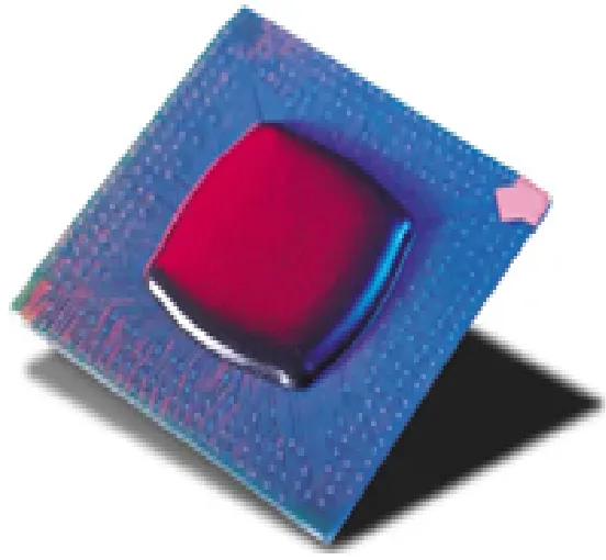
Modern consumer electronics — smartphones, tablets, smartwatches, TWS earbuds and AR/VR headsets — are built around extremely compact semiconductor packages: bare flip-chip dies, wafer-level chip-scale packages (WL-CSP), fan-out wafer-level packages (FOWLP) and system-in-package (SiP) modules. Each of these packages relies on solder bumps or copper pillars with standoff heights as small as 20–50 µm — far smaller than traditional BGA components. Without underfill, repeated thermal cycling and mechanical shock from everyday use concentrates stress on individual bumps, leading to fatigue cracking and field failure.
Chip underfill fills this microscopic gap with a thermoset epoxy that co-cures with the interconnect structure, redistributing stress across the entire die footprint. The result is a 10× or greater improvement in thermal cycle life and significantly higher drop-test pass rates — both critical qualification criteria for consumer OEMs. The challenge for contract manufacturers and IDMs alike is applying this material at sub-milligram volumes with zero contamination of adjacent bond pads, optical elements or RF structures.
SANCO desktop visual dispensing machines and inline high-speed dispensing machines are engineered for exactly this application window — delivering needle-position accuracy to ±0.03 mm, heated barrel stability within ±1 °C, and closed-loop pressure control that maintains consistent bead volume from the first die to the ten-thousandth.
Why Chip Underfill Is Harder Than PCB Underfill
Chip-level underfill operates at dimensions and tolerances an order of magnitude tighter than board-level processes. These are the six key challenges manufacturers face.
Ultra-Low Standoff Gaps (20–50 µm)
Flip-chip and WL-CSP standoffs are 2–4× smaller than BGA components. Underfill viscosity must be below 300–500 mPa·s at dispense temperature to achieve complete capillary fill without voiding, requiring precise barrel temperature control throughout the run.
Die Sizes From 1 mm² to 100 mm²
Consumer electronics chips span an enormous size range — from tiny 1×1 mm RF dies to large 10×10 mm application processors. Each die size requires a different dispensing pattern, bead volume and flow time. SANCO's offline programming handles this automatically from die dimensions entered in the software.
Contamination-Sensitive Adjacent Structures
Consumer IC substrates often carry wire-bond pads, optical apertures, MEMS membranes and RF antenna traces immediately adjacent to the die. Any underfill flash on these structures causes immediate functional failure. Needle positioning accuracy must be within ±0.03 mm to maintain safe keep-out zones.
Multi-Die SiP Substrates
System-in-package modules integrate multiple dies — logic, memory, PMIC, RF — on a single substrate. Each die may need a different underfill material or dispensing pattern, and the narrow inter-die gaps (as little as 100 µm) demand precise toolpath programming to avoid cross-contamination between cavities.
Warpage During Cure
Thermal mismatch between die, underfill and substrate causes warpage during cure, which can open solder joints on adjacent components if not controlled. SANCO supports staged cure profiles and low-CTE underfill formulations to minimise warpage on thin substrates common in wearables and earbuds.
Takt Time Pressure on Advanced Packaging Lines
Advanced packaging lines for flagship consumer devices target takt times below 10 seconds per substrate. SANCO's piezo jetting valve option eliminates needle Z-travel time entirely, enabling non-contact chip underfill dispensing at speeds compatible with the fastest flip-chip attach lines.
Key Capabilities for Chip Underfill Applications
Sub-Milligram Dispense Volume
Minimum dispense volume of 0.001 ml supports the smallest 1×1 mm dies without overflow onto adjacent structures or bond pads.
Barrel Temperature Control ±1 °C
Tight thermal regulation of the material barrel keeps underfill viscosity stable across a full production shift, eliminating flow rate drift that causes voids or excess fillet.
±0.03 mm Needle Positioning
CCD vision alignment corrects for substrate panel distortion and die placement offsets in real time, holding dispensing accuracy well within the keep-out zones of adjacent structures.
Piezo Jetting for Non-Contact Dispense
Optional piezo jetting valve eliminates needle-to-substrate contact entirely — essential for fragile MEMS, optical dies and ultra-thin wafer-level packages where mechanical contact would cause cracking.
Closed-Loop Pressure Feedback
Real-time pressure monitoring auto-compensates for material aging and temperature variation, maintaining constant bead geometry from the first substrate to the last without manual intervention.
Multi-Die Pattern Programming
Program separate dispensing patterns, volumes and keep-out zones for each die on a SiP substrate in a single programme file — no manual switching between recipes during production.
Gerber & CAD Import
Import die layout data directly from Gerber or CSV to auto-generate dispensing toolpaths, reducing new product introduction time for each new consumer IC design entering production.
Inline Flip-Chip Line Integration
SMEMA-compatible conveyor interface allows seamless integration between flip-chip bonder, SANCO underfill station and cure oven — fully automated with zero manual board handling.
The Chip Underfill Process Step by Step
Chip underfill demands tighter process control than board-level underfill. SANCO equipment is calibrated to support every stage from substrate prep through post-cure inspection.
Substrate Preparation & Plasma Clean
Plasma or UV-ozone treatment removes organic contamination and raises surface energy for maximum underfill adhesion on bare substrates.
Die Attach & Reflow
Flip-chip or bare die is attached via solder bump or copper pillar reflow. Coplanarity and standoff uniformity are verified before underfill begins.
Preheat to 80–100 °C
Substrate is preheated to lower underfill viscosity below 500 mPa·s, enabling rapid and complete capillary penetration into 20–50 µm gaps.
Precision Dispensing & Fillet
SANCO machine deposits a micro-volume bead on die edges. Capillary action fills beneath the die; a reinforcing fillet is then applied to all perimeter edges.
Cure & C-SAM Inspection
Thermal cure at 150–165 °C / 30–45 min, or UV-assisted rapid cure. Post-cure acoustic microscopy (C-SAM) verifies void-free fill to OEM specification.
Chip Underfill Material Types & SANCO Compatibility
SANCO dispensing machines handle the full spectrum of chip-level underfill materials used in advanced consumer electronics packaging.
| Material Type | Viscosity Range | Cure Method | Typical Application | SANCO Compatibility |
|---|---|---|---|---|
| Capillary Chip Underfill (CUF) | 100 – 500 mPa·s | Thermal 150–165 °C | Flip-chip on organic substrate; WL-CSP on PCB in smartphones and tablets | Recommended |
| No-Flow Underfill (NUF) | 500 – 3,000 mPa·s | Reflow-activated | Pre-applied beneath bare die before bump reflow; earbuds, wearable SiP | Recommended |
| Wafer-Applied Underfill (WAUF) | 200 – 1,000 mPa·s | Thermal or UV | Applied at wafer level before dicing; FOWLP and advanced node mobile SoCs | Recommended |
| SiP Multi-Die Underfill | 300 – 2,000 mPa·s | Staged thermal cure | Individual die underfill within multi-chip SiP modules; smartwatches, TWS ICs | Recommended |
| Reworkable Chip Underfill | 1,000 – 5,000 mPa·s | Thermal 125–140 °C | Prototype and low-volume runs; high-value dies requiring rework capability | Recommended |
Frequently Asked Questions
What is the smallest die size that SANCO dispensing machines can underfill?
SANCO desktop visual dispensing machines support minimum dispense volumes of 0.001 ml with 30G needle gauges, enabling reliable capillary underfill on dies as small as 1×1 mm — including the smallest RF and PMIC dies found in TWS earbud and smartwatch SiP modules. Contact our application engineers to validate your specific die geometry and standoff specification.
What is the difference between chip underfill and PCB underfill?
Chip underfill refers to underfill applied directly beneath a bare die or wafer-level package on a substrate — standoff gaps are typically 20–50 µm and underfill viscosity must be extremely low (100–500 mPa·s) for complete capillary fill. PCB underfill applies to board-level BGA and CSP packages with larger standoff gaps of 100–300 µm and can use higher-viscosity materials. SANCO dispensing machines support both processes through interchangeable valve heads and adjustable barrel temperature.
Can SANCO machines handle multi-die SiP substrates with different underfill patterns per die?
Yes. SANCO's offline programming software allows engineers to define individual dispensing patterns, bead volumes, keep-out zones and cure profiles for each die on a SiP substrate within a single programme file. The machine executes each die's pattern sequentially in one pass without operator intervention or recipe switching.
Is non-contact piezo jetting available for chip underfill?
Yes. SANCO offers a piezo jetting valve option that dispenses underfill as micro-droplets without needle contact. This is the preferred method for MEMS dies, optical packages and ultra-thin wafer-level packages where needle contact carries cracking risk. Jetting also eliminates needle Z-travel time, reducing cycle time by up to 40% on multi-die substrates.
How does SANCO equipment prevent underfill voiding beneath flip-chip dies?
Voids are primarily caused by insufficient substrate preheating, incorrect bead placement or material viscosity drift. SANCO addresses all three: the heated stage maintains substrate temperature within ±2 °C throughout dispensing; CCD vision places the bead within ±0.03 mm of the target die edge; and closed-loop pressure control compensates for material viscosity change as the barrel cools or ages. For applications with strict void specifications (below 1% by C-SAM), our application engineers can assist with process recipe development and validation.
Where can I learn about other consumer electronics packaging applications?
Visit our Applications section for detailed guides covering PCB underfill, camera module bonding, speaker sealing, SMT surface mounting and more consumer electronics processes. For equipment specifications, see our dispensing machine product pages.